Double Offset Valve Design Standards and Specifications
Double Offset Valve Design Standards and Specifications
Double offset valves, also called double offset butterfly valves or high performance butterfly valves, are widely used in modern process industries. Understanding their design standards and specifications is essential for engineering, procurement, installation, and long‑term operation. This guide presents industry‑generic, standards‑based information suitable for technical reference, industrial catalogs, and engineering blogs.
1. What Is a Double Offset Valve?
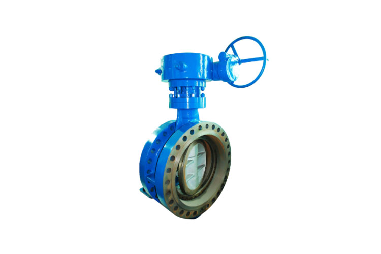
A double offset valve is a type of butterfly valve in which the disc is offset in two distinct ways from the valve centerline. Compared with concentric butterfly valves, this double eccentric geometry reduces friction between the disc and seat during opening and closing, allowing higher pressure ratings, tighter shut‑off, and longer service life.
1.1 Double Offset Geometry Explained
The term “double offset” refers to two eccentricities:
- First offset: The valve stem (shaft) is offset from the centerline of the disc.
- Second offset: The valve stem is also offset from the centerline of the pipeline (the flow path).
This double eccentricity causes the disc to move away from the seat quickly as it begins to open, minimizing sliding contact and reducing wear on the sealing surfaces.
1.2 Double Offset vs Triple Offset vs Concentric
Feature |
Concentric Butterfly Valve |
Double Offset Butterfly Valve |
Triple Offset Butterfly Valve |
Disc / shaft position |
Disc center and shaft on pipe centerline |
Shaft offset from disc center and pipe centerline |
Double offset plus a third angular offset (conical seat) |
Typical pressure rating |
Low to medium |
Medium to high |
High and severe service |
Shut‑off performance |
Good, mainly for low pressure |
Very good, bubble‑tight achievable |
Excellent, zero leakage (metal‑to‑metal) |
Seat type |
Resilient soft seat |
Soft seat or metal‑seated high performance |
Metal‑to‑metal with conical geometry |
Typical applications |
Water, HVAC, general low pressure |
Oil & gas, power, process, steam |
High temperature, high pressure, critical isolation |
1.3 Typical Applications of Double Offset Valves
- Oil and gas transmission and distribution
- Refining and petrochemical plants
- Chemical and process industries
- Power generation (including steam and condensate systems)
- District heating and cooling systems
- Water treatment and desalination plants
- Marine and offshore applications
2. Key Design Features of Double Offset Valves
Several features define the design of double offset valves and are reflected in design standards and specifications.
2.1 Body Design and End Connections
- Wafer body
- Lug body
- Flanged body (single or double‑flanged)
- Butt‑weld or socket‑weld ends (less common, but used in specific process applications)
End connection details typically follow recognized flange and piping standards such as ASME, EN, and ISO norms (covered later in this article).
2.2 Disc and Shaft Construction
The disc of a double offset butterfly valve is streamlined to minimize pressure loss while providing sufficient strength. Common design considerations include:
- Low torque design to reduce actuator size
- Optimized disc profile for flow efficiency
- Rigid connection between disc and shaft
- Blow‑out proof shaft design
2.3 Seat Design
Seat design is critical for shut‑off and durability. Double offset valves may employ:
- Soft seats (e.g., PTFE, reinforced PTFE, elastomers) for bubble‑tight shut‑off, low torque, and chemical resistance.
- Metal seats (e.g., stainless steel overlays, hard‑faced alloys) for higher temperatures and more severe service, sometimes with flexible or laminated metal seating elements.
The double offset geometry ensures that the seat is contacted primarily at the closed position, reducing wear compared to concentric designs.
2.4 Stem Sealing and Bearing System
Stem sealing is usually achieved by a combination of packing and gaskets, while bearings support the shaft. Typical features:
- Live‑loaded packing for long‑term sealing performance
- Low‑friction bearings to reduce operating torque
- Corrosion‑resistant bearing materials or coatings
- Anti‑blowout stem retention
3. Relevant Design Standards for Double Offset Valves
Double offset valves are designed and manufactured in accordance with several international standards. These standards define dimensions, face‑to‑face lengths, pressure ratings, testing requirements, and terminology.
3.1 API 609 – Butterfly Valves: Double‑Flanged, Lug‑ and Wafer‑Type
API 609 is a primary reference for industrial butterfly valves. It has two categories:
- Category A: Generally concentric, resilient‑seated valves.
- Category B: High‑performance valves including double offset designs.
Key aspects of API 609 for double offset valves include:
- Pressure‑temperature ratings
- Face‑to‑face dimensions
- Body end connection details (wafer, lug, double‑flanged)
- Minimum wall thickness
- Testing and inspection requirements
3.2 EN 593 – Industrial Valves: Metallic Butterfly Valves
EN 593 specifies requirements for metallic butterfly valves, including those with double offset design, used for isolating and regulating service in industrial applications.
3.3 ISO 5752 – Face‑to‑Face and Center‑to‑Face Dimensions
ISO 5752 provides series of face‑to‑face and center‑to‑face dimensions for butterfly valves. It ensures interchangeability between manufacturers when valves of the same nominal size and series are used.
3.4 ISO 5211 – Mounting Flanges for Actuators
ISO 5211 defines the interface between industrial valves and actuators. Double offset valves often include ISO 5211 actuator mounting pads for standardized direct or bracket‑mounted actuators.
3.5 Other Related Standards
Standard |
Title / Scope |
Relevance for Double Offset Valves |
ASME B16.5 |
Pipe Flanges and Flanged Fittings |
Defines flange dimensions and pressure classes (e.g., Class 150, 300) |
ASME B16.47 |
Large Diameter Steel Flanges |
Flange dimensions for larger size double offset valves |
EN 1092‑1 |
Flanges and their Joints – Circular Flanges |
European flange standards (PN ratings) for flanged valves |
ISO 5208 |
Industrial Valves – Pressure Testing of Metallic Valves |
Leakage rates and pressure test procedures |
ISO 10434 / API 600 |
Bolted Bonnet Steel Gate Valves (reference) |
Sometimes referenced for material and pressure‑temperature ratings |
ISO 15848 |
Fugitive Emissions Testing |
Stem sealing performance in environmental applications |
EN 12266‑1 / EN 12266‑2 |
Industrial Valves – Testing |
European pressure and leak testing requirements |
API 598 |
Valve Inspection and Testing |
Widely used leak, shell, and seat testing requirements |
4. Typical Double Offset Valve Specifications
Double offset valve specifications usually include size range, pressure rating, temperature range, materials, end connections, and performance data. The following tables summarize typical specification ranges for industrial use. Actual values depend on product design and selected standards.
4.1 Size and Pressure Rating
Parameter |
Typical Range |
Notes |
Nominal Diameter (DN) |
DN 50 – DN 2000 |
Smaller and larger sizes possible depending on design |
Nominal Pipe Size (NPS) |
2″ – 80″ |
Common for high performance double offset valves |
ASME Pressure Class |
Class 150, 300, 600 (occasionally higher) |
Defined in ASME B16.5 / B16.47 |
EN / ISO Pressure Rating |
PN 10 – PN 40 (sometimes PN 63 / PN 100) |
Defined in EN 1092‑1 and related standards |
4.2 Temperature and Media
Design Feature |
Typical Range / Properties |
Considerations |
Operating Temperature (soft seat) |
‑40 °C to +200 °C (approx.) |
Depends on seat material (e.g., EPDM, NBR, PTFE) |
Operating Temperature (metal seat) |
Up to 400–600 °C (application dependent) |
Requires high‑temperature design and materials |
Typical media |
Water, steam, hydrocarbons, gases, chemicals |
Material selection based on fluid compatibility |
Corrosive service |
Available with stainless or alloy trims |
Seat, disc, and body material carefully specified |
4.3 Face‑to‑Face Dimensions (Reference)
Face‑to‑face dimensions of double offset valves generally follow:
- API 609 (Category B)
- ISO 5752 (Series 13, 14, etc.)
- EN 558 (series corresponding to butterfly valves)
These standards ensure that valves can be interchanged without major piping modifications.
5. Materials of Construction
Material selection for double offset valves is driven by design standards, process media, pressure, temperature, and required lifespan.
5.1 Common Body Materials
Material |
Typical Designation |
Characteristics |
Typical Use |
Carbon Steel |
ASTM A216 WCB or equivalent |
Good strength, economical |
General industrial service, hydrocarbons |
Low Temperature Carbon Steel |
ASTM A352 LCB / LCC |
Improved toughness at low temperature |
Low temperature services, cryogenic lines (with specific design) |
Stainless Steel |
ASTM A351 CF8 / CF8M |
Corrosion resistance |
Chemicals, water treatment, corrosive media |
Duplex Stainless Steel |
ASTM A995 Gr. 4A / 5A, etc. |
High strength and corrosion resistance |
Chloride‑rich environments, seawater, offshore |
Alloy Steels |
Various Cr‑Mo alloys |
High temperature strength |
Power generation, high temperature steam |
5.2 Disc and Shaft Materials
The disc and shaft require materials that combine strength, corrosion resistance, and manageable weight:
- Stainless steels (e.g., 304, 316) for general corrosion resistance.
- Duplex or super duplex stainless steels for seawater or aggressive brines.
- High alloy materials for corrosive or high‑temperature media.
- Nickel‑based alloys where extreme corrosion resistance is required.
5.3 Seat Materials
Seat Material |
Type |
Temperature Capability |
Typical Application |
EPDM |
Elastomer (soft) |
Approx. ‑30 °C to +120 °C |
Water, some chemicals, HVAC |
NBR (Nitrile) |
Elastomer (soft) |
Approx. ‑20 °C to +100 °C |
Oils, hydrocarbons |
PTFE |
Polymer (soft) |
Approx. ‑40 °C to +200 °C |
Chemicals, clean services |
Reinforced PTFE / RPTFE |
Polymer composite |
Enhanced vs PTFE |
Improved wear and deformation resistance |
Metal seat (Stainless, Stellite, etc.) |
Metallic |
High temperature, up to 400–600 °C |
Steam, high temperature, abrasive or severe service |
5.4 Gaskets, Packing, and Bearings
- Packing: Graphite, PTFE, or combination sets for stem sealing, often designed to meet low fugitive emission requirements.
- Gaskets: Spiral wound, compressed fiber, or graphite for body joints and bonnet connections (if applicable).
- Bearings: Bronze, PTFE‑lined, or composite materials to reduce friction and resist corrosion.
6. Performance, Advantages, and Limitations
Double offset valves occupy an important position between standard concentric butterfly valves and more complex triple offset valves or other isolation valves.
6.1 Key Advantages
- Improved sealing performance: Double offset design allows tight shut‑off, often meeting leakage class standards such as API 598 or ISO 5208 Rate A (bubble‑tight for soft seats).
- Reduced seat wear: Minimal sliding friction between disc and seat extends service life and reduces maintenance.
- Lower operating torque: Efficient geometry and seat contact reduce required actuator size.
- Compact and lightweight: Compared with gate or globe valves of similar pressure class, double offset valves are generally more compact and lighter.
- Bi‑directional sealing: Many designs provide tight shut‑off in both directions of flow, subject to design verification.
- Suitability for automation: ISO 5211 mounting pads and low torque make them ideal for automatic control or remote operation.
6.2 Potential Limitations
- Not always suitable for severe throttling where cavitation or flashing is expected.
- Pressure and temperature ranges are generally lower than heavy‑duty triple offset or gate valves in the highest classes.
- Disc in the flow path may not be acceptable for some slurry or highly abrasive services without specific design measures.
7. Testing and Inspection Requirements
Double offset valve design standards specify mandatory pressure testing and inspection to ensure performance and safety.
7.1 Pressure and Leakage Tests
Common standards used for testing include API 598, ISO 5208, EN 12266‑1, and EN 12266‑2. Typical tests are:
- Shell test: Hydrostatic test at a specified multiple of rated pressure to verify body strength.
- Seat leakage test: Hydrostatic or pneumatic test to demonstrate shut‑off capability and define leakage rate class.
- Backseat test (if applicable): For designs incorporating backseat features.
- Operational tests: Cycling the valve through open/close operations to confirm smooth movement and correct travel.
7.2 Leakage Rate Classes
Standard / Class |
Description |
Application to Double Offset Valves |
API 598 |
Standard test; generally bubble‑tight for soft seats |
Widely adopted; many double offset valves designed to pass zero visible leakage |
ISO 5208 Rate A |
No visible leakage (bubble‑tight) |
Soft‑seated double offset valves commonly meet this class |
ISO 5208 Rate B–F |
Permitted leakage depending on class |
Metal‑seated valves may be specified to these leakage rates |
EN 12266‑1 |
Similar classification approach |
Used in European projects and specifications |
7.3 Optional and Special Tests
- Fire type testing (API 607, ISO 10497 or equivalent) for fire‑safe designs.
- Fugitive emission testing (ISO 15848, API 641) for environmental compliance.
- Low temperature / cryogenic testing to verify performance at sub‑zero temperatures.
- Nondestructive examination (NDE) such as radiography, magnetic particle examination, liquid penetrant testing, and ultrasonic testing for body and weld integrity.
8. End Connections and Installation Standards
Proper specification of end connections ensures compatibility with piping systems and compliance with pressure‑temperature ratings.
8.1 Wafer, Lug, and Flanged Ends
- Wafer type: Designed to be sandwiched between flanges; suitable for compact installations.
- Lug type: Incorporates threaded or through‑holes for bolting; allows dead‑end service in some designs.
- Double‑flanged type: Flange faces integrated into the body; robust and suitable for demanding conditions, large sizes, or buried service.
8.2 Flange Standards
Region / Standard |
Flange Norms |
Pressure Designation |
ASME / ANSI |
ASME B16.5, ASME B16.47 |
Class 150, 300, 600, etc. |
European (EN) |
EN 1092‑1 |
PN 10, PN 16, PN 25, PN 40, PN 63, PN 100 |
ISO / International |
ISO 7005 |
PN rating system aligned with EN |
8.3 Installation Considerations
- Ensure correct alignment between valve and pipeline flanges.
- Confirm that disc can open fully without contacting downstream piping or equipment.
- Observe flow direction requirements if the valve is not symmetrical.
- Provide sufficient space for actuator and manual operation.
- Follow torque values for flange bolting as per flange standards.
9. Actuation and Control Options
Double offset valves are ideal for automation due to low torque and standardized actuator interfaces.
9.1 Manual Operation
- Hand lever for smaller sizes and lower pressure ratings.
- Gearbox (worm gear) for larger valves or higher torques, providing mechanical advantage and position indication.
9.2 Automated Actuation
Actuator Type |
Characteristics |
Typical Applications |
Pneumatic (quarter‑turn) |
Fast response, suitable for on/off and modulating control |
Process control, safety shutdown systems |
Electric actuator |
Precise control, suitable where air supply is limited |
Water treatment plants, building services |
Hydraulic actuator |
High torque, robust for offshore or subsea applications |
Large size valves, critical isolation, remote locations |
9.3 Mounting Standards
ISO 5211 ensures compatibility between the valve topworks and actuator. Relevant parameters include:
- Flange size and bolt pattern on the valve top.
- Driving stem dimensions (e.g., square, keyed connections).
- Torsional capacity required to operate the valve at maximum differential pressure.
10. Selection Guidelines Based on Standards and Specifications
Proper selection of a double offset valve requires alignment of process conditions with applicable standards and specifications.
10.1 Key Selection Parameters
- Nominal size and connection standard (ASME Class or EN PN).
- Design and operating pressure and temperature.
- Fluid characteristics (corrosive, erosive, clean, slurry, gas, liquid).
- Required leakage class or shut‑off performance.
- Fire‑safe and fugitive emission requirements (if any).
- Installation orientation and available space.
- Actuation type and control philosophy (on/off vs modulating).
10.2 Example Specification Framework
A typical technical specification for a double offset butterfly valve might include:
- Valve type: Double offset high performance butterfly valve.
- Design standard: API 609 Category B or EN 593.
- Face‑to‑face: ISO 5752 / EN 558 corresponding series.
- Pressure class: ASME Class 150 / 300 / 600 or PN 16 / PN 25 / PN 40.
- End connection: Wafer / Lug / Double‑flanged to ASME B16.5 or EN 1092‑1.
- Body material: Carbon steel / stainless steel / duplex etc.
- Disc material: Stainless steel or alloy steel.
- Seat material: PTFE / RPTFE / elastomer / metal seat.
- Stem and sealing: Stainless shaft with graphite or PTFE packing.
- Testing: API 598 or ISO 5208, leakage class as specified.
- Fire‑safe design: If required, tested to API 607 or equivalent.
- Actuator and accessories: Per ISO 5211 interface; limit switches, positioners, or solenoids as required.
11. Comparison with Other Valve Types
In many systems, engineers compare double offset valves with gate, globe, ball, and triple offset valves to determine the optimal solution.
11.1 Comparison Table
Valve Type |
Shut‑off Performance |
Pressure / Temperature Capability |
Flow Control (Throttling) |
Size / Weight |
Double Offset Butterfly |
Very good, often bubble‑tight with soft seat |
Medium to high |
Acceptable for many services |
Compact and lightweight |
Triple Offset Butterfly |
Excellent, metal‑to‑metal zero leakage |
High and severe service |
Good for control in some designs |
Compact but usually higher cost |
Gate Valve |
Good isolation |
High pressure and temperature |
Not suitable for throttling |
Larger and heavier |
Globe Valve |
Good shut‑off |
High pressure and temperature |
Excellent for throttling |
Heavier and higher pressure drop |
Ball Valve |
Excellent shut‑off |
High pressure and temperature |
Limited throttling capability |
More compact than gate/globe but heavier than butterfly |
12. Documentation and Compliance
Double offset valves supplied for industrial projects often require comprehensive documentation in line with design standards and specifications.
12.1 Typical Documentation Package
- General arrangement drawing with key dimensions.
- Bill of materials identifying all wetted and pressure‑retaining parts.
- Pressure‑temperature rating tables according to standards.
- Material certificates (e.g., EN 10204 3.1 / 3.2).
- Test reports (hydrostatic, seat leakage, optional special tests).
- Installation, operation, and maintenance manual (IOM).
- Certificates for fire‑safe or fugitive emission compliance where applicable.
Double offset valves, also known as high performance butterfly valves, provide a standardized, efficient solution for isolation and control in a wide range of industrial applications. By aligning design, materials, testing, and actuation with recognized international standards such as API 609, EN 593, ISO 5752, ISO 5208, and EN 12266, engineers can ensure compatibility, reliability, and regulatory compliance.
When specifying a double offset valve, attention to size, pressure class, material selection, seat type, leakage class, and actuator interface is essential. Using the design standards and specification guidelines outlined in this article helps create robust, repeatable, and documentable valve selections that integrate smoothly into complex piping systems and process plants.
“`






 Phone